
GIXpresso
The
About the Mug

About the Machine
The GIXpresso Mug
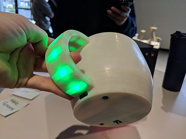
The mug is designed with GIX famous "X" logo and a connection point at the bottom of the cup. It contains lights that indicate whether the coffee is idle or being filled.
The mug is idle when the LED strips are green and red when being filled.
The GIXpresso Machine
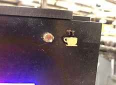
The machine is designed to fit the mug with a secure fit of the GIX "X" and a connection point at the bottom of the filling station.
A light guide indicates whether the machine is brewing or not. A LED strip glows red when it is not filling and glows red/green/blue when it is filling.
Introducing gixpresso
low/med fidelity prototype


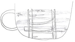
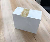
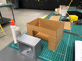
In order to get the high level description of our coffee machine and mug, we developed a low fidelity prototype out of cardboard and paper.
The light guides are shown in pen.
-
Mug - On the handle
-
Machine - "Brewing" indicator (front top right)

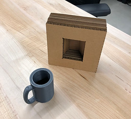

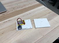
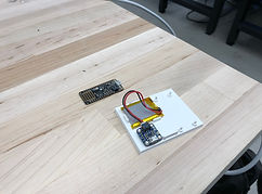
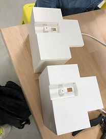
Then we moved onto a medium fidelity prototype. We removed the box machine as a separate enclosure and focused on two parts: 1) the mug and 2) the filling station.
For the mug, we 3D printed a mug. The filling station was created by adding layers of laser cut cardboard squares
Making The
Mug
Configuring the components
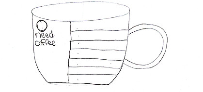
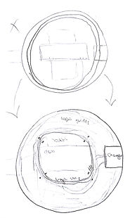
We began by sketching where the lights would go on the mug. We wanted the effect of lights turning on going up the mug to simulate the mug being filled with coffee.


One idea we had was to place the Playground Board on the top of the mug and create guides to bend the light 90 degrees and bring it to the surface.
The next idea we had was to stack all the components in the middle of the cup, however, it would be difficult to secure the components like this and the inside of the mug would be completely filled with hardware.

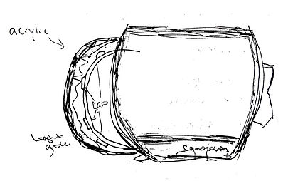
Finally, we decided to configure all the components at the bottom of the mug to allow room for coffee, run a strip of LEDs up the handle with acrylic guides leading the light out, and add the GIX logo to the front of the mug to allow for a key fit into the machine.
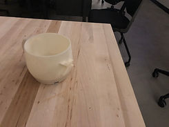
first print


The first print on the Ultimaker was larger than we expected, but the proportions of the cup were nice.

Charger
Battery
Connection
Arduino
Feather
Room for wires and LED strip
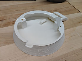
The first iteration of the bottom piece did not fit all the components as nicely as we would have liked.
revisions

We created a list of things to fix on the model before printing our second iteration.
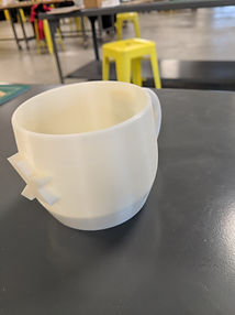
Second print
For our second print, we decided to only print the bottom part that was essential for testing the fit of the components. Also, underneath the top part, we added places for screws to connect the two pieces.

Revisions

third print
The third print focuses on the bottom piece, and we printed two versions to determine the best fit for all the components.

fastening the leds
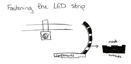
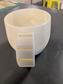
After researching and sketching different ways to fasten the LED strip in the mug's handle, we decided the most discreet way would be to make the pieces between the holes almost completely solid to create a tight fit.

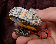
The LED strip successfully threads into place. In this photo there are two LED strips, however for the final mug we decided that one strip was plenty bright.
Fourth print

On the fourth print, the components successfully stay in place!


For this iteration, we again decided to only print the parts that would be most useful to us for determining fit. The photo on the right shows all the component screwed into the mug.

This iteration has part of the GIX logo printed so that we could asses general fit. After a bit of sanding on both parts we began to see a good fit, so we made adjustments to both pieces on our CAD files.
Creating the light guides

The light guides are laser cut pieces of acrylic that will fit in the holes on the handle. The holes are designed so that two layers of acrylic will fit in with a snug fit so they won't come loose.

Above is the initial design of the light guide with pieces on both sides to squeeze when it is put in then act as a barrier to keep from coming out. However the acrylic was too brittle and kept snapping when squeezed, so the final design of the light guides is below.

Final print
The final print was created with a stratasys f170. The higher fidelity of this printer was immediately obvious.
Still, we spent 6 hours sanding the mug up to 12,000 grit to achieve a very smooth and shiny surface similar to a ceramic mug.
Final Assembly

We are extremely happy with how the final mug turned out. All the component fit nicely into the bottom of the water-tight mug, the connection is a nice snap fit, and the power switch is nicely hidden under the handle.
hardware

Software
Making The
Machine
designing the shape


In order to get the snug fit from the mug, we designed the Machine so it only accepts the smart mug.
Here are the original sketches for our planned smart coffee machine

First print


This showcases our deep dive into 3D printing with the ultimakers. They're prone to messing up and it shows in our gray machine models above.

Here is a completed first print version of the machine with no connection point.
Second print

For our second print, we were able to design the connection point...however, the ultimaker was acting up and we ended up with a 3/4 part done.
Side note: the faulty section was really squishy and fun to play with.


We then decided to use .8 PLA/PVA and ended up with a solid second print finish. We were able to use this as a guider for the Mug.
The connection point is clearly visible and able to connect to the mug.

Printing the component holder


Once again the dreaded ultimaker printed out a failed component holder. However no additional revisions were needed and the reprint took under 2 hours.
With the second print of the component holder done, we were able to test out the fit for pieces. All in all, it held up pretty well, with only a few revisions to hold in the feather.
Revisions
After the first two prints, we needed to pinpoint the needed revisions:
-
Make the "X" shape allowance larger
-
Re-measure arduino feather
-
Modify code to show light on when connected
-
Have feather and battery connection on edge of holder
third print


The third print is considered the final print (other than the f170 print). The ultimaker did a pretty good job other than the faulty hexnut sealer.
Next was actually testing the connection port and it was successful!
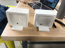
Enclosure development
The f170 printed part came out and it was much more defined and properly structured than the ultimaker. Above is a side by side comparison.


Initial sketch of the Machine for mug fit. This was started after we got a working fit of our cup enclosure.
woodworking
In order to visualize what the Machine enclosure would look like, we created a cardboard low fidelity
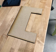

After our low fidelity make of the Machine, we started off laser cutting the medium density fiberboard and started to form fit everything.


Spray painting our woodwork black and gluing the Machine shut with clamps was by far one of the funnest activities. Minus the whole inhaling super glue fumes.

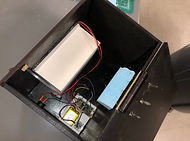
Here is the finished Machine box (sans roof)
Creating the light guides


Next was the light guide to indicate that our coffee was brewing to the cup once the interaction was made.

We tried a right triangle but realized light escaped. We then transitioned to a curved light guide made from acrylic.
The light now shows when the Mug is inserted and the coffee is brewing.
Adding the top

hardware
Finally we sealed off the internal components by adding a top to our machine enclosure, held together with a hinge.
With that we were done with the Machine!

Software

Finished Product

The showcase and final product!

Meet The Team

Adele Parsons
Mastermind of the Mug

Michael Lai
Mastermind of the Machine